What is galvanometer? Physics learn: tangent galvanometer, physics practical std 11 & 12 gseb Galvanometer principle
What is a Galvanometer ? Principle, Construction and Working
Using a galvanometer to detect & measure electric current Circuit diagram for conversion of galvanometer into ammeter Tangent galvanometer physics experiment construction practical apparatus magnet connect pivoted digram line learn compass key box
17 best ammeter design using galvanometer for trend 2022
Horizontal component of earth’s magnetic field using tangentSolved look at figure 22-2 (schematic of tangent Galvanometer scheme circuit curid fred oyster wikimedia sa commons cc file index phpGalvanometer ammeter resistance circuit into conversion used construction definition working potential shunt voltage equal parallel difference wire between low principle.
Galvanometer coil moving construction parts magnet suspension principle circuit working definition main permanent circuitglobeGalvanometer circuit diagram Galvanometer circuit diagramFigure shows two circuits each having a galvanometer and a battery of 3.

To determine the resistance of a galvanometer by a half-detection
Galvanometer circuit diagramCircuit diagram for conversion of galvanometer into ammeter Galvanometer – gaugehow mechanical engineeringGalvanometer voltmeter coil resistance principle.
Moving coil galvanometer circuit diagram(a) briefly explain how a galvanometer is converted into a voltmeter Galvanometer diagramGalvanometer circuit diagram.

Ammeter circuit diagram galvanometer
Galvanometer voltmeter ammeter angle pngwing schematicTangent galvanometer : theory and construction of tangent galvanometer Ammeter circuit diagram galvanometerGalvanometer diagram.
Circuit diagram of galvanometer to ammeterThe sensitivity of a moving coil galvanometer increases with the Galvanometer tangent magnetic field earth physics project follows initial adjustments doneGalvanometer circuit diagram.

Galvanometer circuit diagram voltmeter ammeter png, clipart, ammeter
Tangent galvanometerExample in the following circuit diagram, the galvanometer reading is zer.. To study the earth's magnetic field using a tangent galvanometerTangent galvanometer figure law schematic look savart biot using show get solved.
Galvanometer coil principleToppr galvanometer draw diagram What is a galvanometerWhat is a galvanometer ? principle, construction and working.
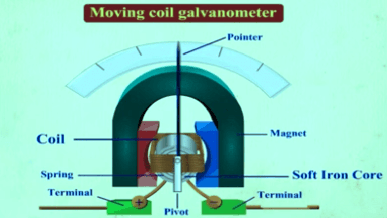
Er. ashish das portal: moving coil galvanometer
Draw the diagram of galvanometer. toppr.comWhat is galvanometer? Galvanometer measure circuit detect electric current using study shunt diagram.
.


Using a Galvanometer to Detect & Measure Electric Current | Study.com

Solved Look at figure 22-2 (Schematic of tangent | Chegg.com

To Study the earth's magnetic field using a tangent galvanometer

Circuit Diagram For Conversion Of Galvanometer Into Ammeter - Circuit

Tangent galvanometer : Theory and Construction of Tangent galvanometer

Galvanometer - Types, Working Principle, Moving Coil Galvanometer and

To Determine The Resistance Of A Galvanometer By A Half-detection